
How ahout the DC charging or DC fast charging for electric vehicles? In this blog we are going to learn about three things: First, what are the key parts of an DC charger. Second, what types of connectors are used for DC charging and third what are the limitations of DC fast charging.
What are the key part of DC charging?
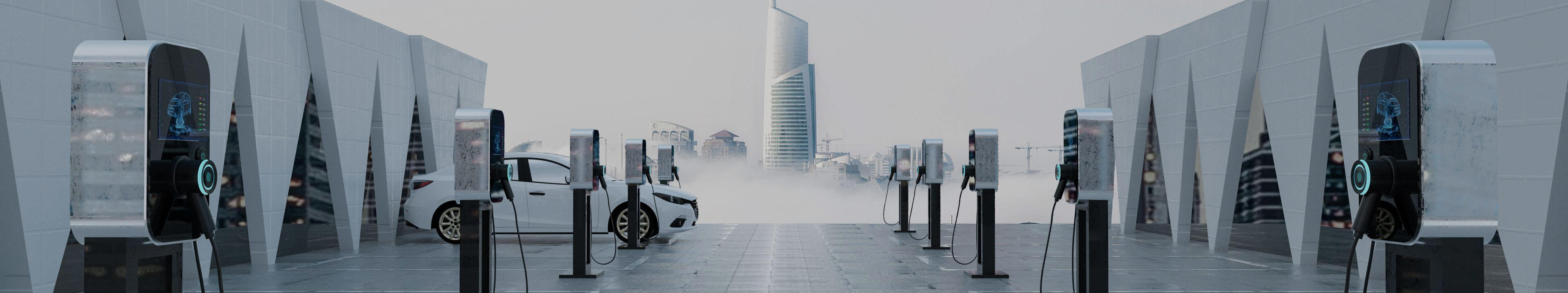
First of all let’s have a look at what are the key parts of a DC charger. DC fast chargers typically operate at level three charging powers and are designed to charge electric vectors quickly, with an electric output ranging between 50 kilowatts to 350 kilowatts, with higher power operation the ac to DC converter. The DC to DC converter and the power control circuits become larger and more expensive,this is why DC fast charger implemented as all forced chargers rather than as own bought chargers. So that it does not take up space within the vehicle and the fast charger can be shared by many users.
Now let us analyze the power flow for DC charging from the DC charger to the electric vehicle battery. In the first step, the alternating current or ac power provided by the ac grid is first converted into direct current or DC power using a rectifier inside the DC charging station. Then the power control unit appropriately adjusts the voltage and current of a DC converter to control the variable DC power delivered to charge the battery.
There are safety interlocks and protection circuits used to de-energize the av connector and to stop the charging process. Whenever there’s a fault condition or an improper connection between the ev and the charger the battery management system or the bms plays the key role of communicating between the charging station and to control the voltage and current deliver to the battery and to operate the protection circuit in case of an unsafe situation. For example, control area network shortly refer to a scan or power line communication shortly refer to as plc are used for communication between the ev and the charger now that you have a basic idea of how a DC charger is configured. Then let us look at the main DC charger connector types there are five types of DC charging connectors used globally.
What type of connectors are use for DC charging?
First is the ccs or the combined charging system called the combo one connector which is mainly used in the u.s. The second is a ccs combo 2 connector which is mainly used in europe. The third is asha demo connector used globally for cars built by japanese manufacturers predominantly fourth the ds tesla DC connector which are used for ac charging as well and finally china has own DC connector based on the chinese gbt standard.
Let us now look at these connectors one by one the combined charging system or ccs connectors also refer to as combo r integral integrated connectors for both ac and DC charging that derived from type 1 and type 2 connectors for ac charging by adding two extra pins at the bottom for high current DC charging. The connectors derived from type 1 and type 2 are respectively called as combo 1 and combo 2.
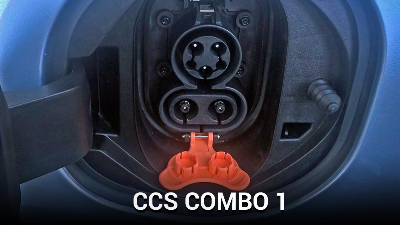
Let us first look at the ccs combo 1 connector in this slide, the combo 1 vehicle connected is shown on the left side and the vehicle inlet is shown on the right side, the vehicle connector of combo 1 is derived of the ac type 1 connector and retains the earth pin and the 2 signal pins namely the control pilot and the proximity pilot in addition to DC power pins are added for fast charging at the bottom of the connector.
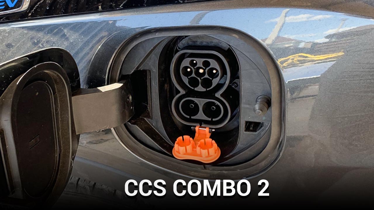
On the vehicle inlet the pin configuration the upper part the same as the ac type 1 connector for ac charging while the bottom 2 pins are used for DC charging similarly. The ccs combo two connectors are derived from the ac type two connectors and retain the earth pin and the two signal pins namely the control pilot on the proximity pilot to DC power pins are added at the bottom of the connector for high-power DC charging similarly.
On the vehicle in that side the upper part facilitates the ac charging from three-phase ac and at the bottom part. You have the DC charging unlike type 1 and type 2 connectors that uses only pulse width modulation or pwm signal signaling on the control pilot the power line communication of plc is used both in the combo 1 and combo 2 chargers and this is produced on the control.
Pilot power line communication is a technology that carries data for communication on existing power lines used for simultaneous transfer of both signal and power transmission the ccs combo chargers can deliver up to 350 amps at a voltage between 200 to 1000 volts. Giving a maximum output power of 350 kilowatts it must be kept in mind that these values are continuously updated by the charging standards to cater to voltage and power requirements of new electric cars. The third DC charger type is the shadow connector which is a type 4 eb connector it has three power pins and six signal pins for this operation. The shidae moe uses the control area network or kin protocol in the communication pins for communication.
Between the charger and the car a control area network communication is a robust vehicle communication standard decide to allow microcontrollers and devices to communicate each other in real-time. Without a host computer as of now the voltage and current and power levels of the shada moe are ranging from 50 to 400 volts with a current up to 400 amps thus providing, a peak power of up to 200 kilowatts for charging in the future.
It is expected that eb charging up to 1,000 volts and 400 kilowatts will be facilitated by a demo now. Let’s move on to tesla charger connectors, the tesla supercharger network in the united states uses their own propriety charger connector while the european variant uses a type 2 minoccurs connector but with DC charging built-in the unique aspect of tesla connector is as the same connector can be used for both ac charging and DC charging tesla now. Offers DC charging up to 120 kilowatts and this is expected to increase in the future.
What are the limitations of DC fast Charging?
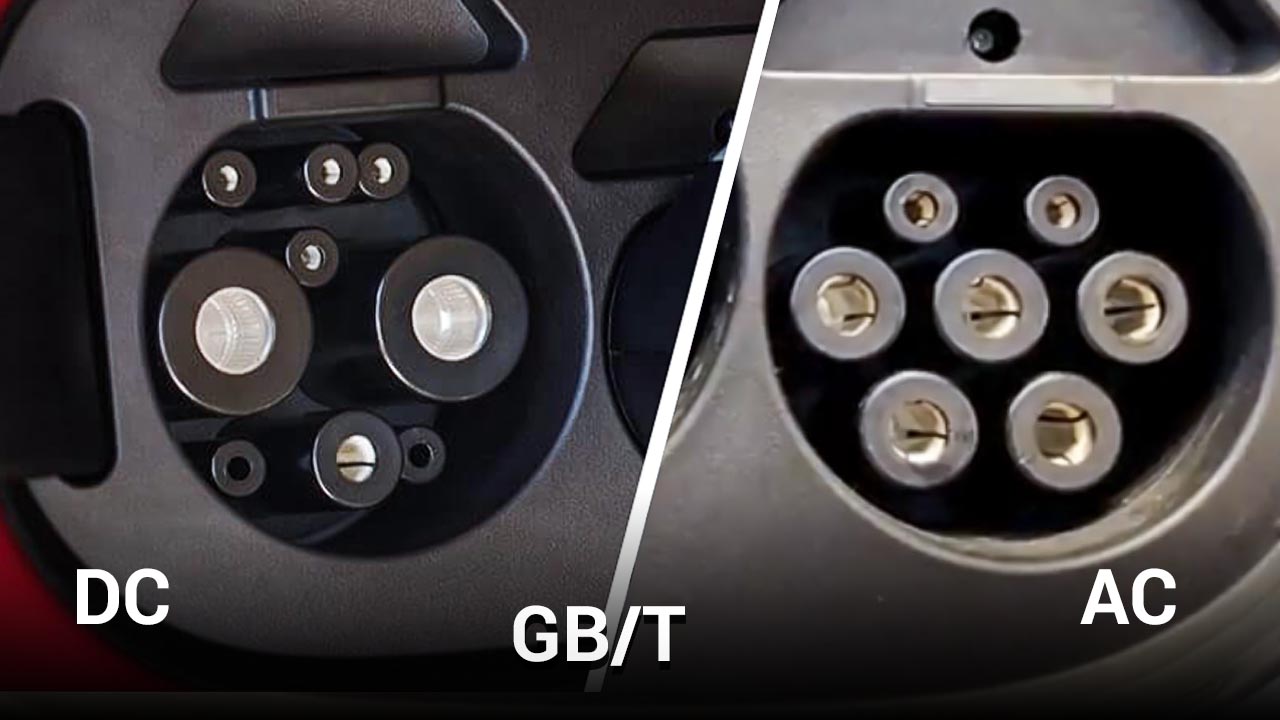
Finally, china has new DC charging standard and connector that uses can bus control area network. Bus come in for communication it has five power pins two for DC power and two for low-voltage auxiliary power transfer and one for ground and it has four signal pins two for the proximity pilot and two for the control area network communication. As of now the nominal voltage used for this connector or 750 volts or 1000 volts and the current up to 250 amps is supported by this charger. It can already see fast charging is quite attractive because of the very high charging powers going all the way up to 300 or 400 kilowatts.
This results in very short charging times but fast charging power cannot be increased infinitely, this is due to three technical limitations of fast charging. Let us now look at these limitations first of all high current charging leads to high overall losses both in the charger and in the battery.
For example, if the internal resistance of a battery is r and the losses in the battery can be expressed simply using the formula i squared r where i is a charging current then you will notice that the losses increased by a factor of four times. Whenever, current is doubled secondly the second limitation further is coming from the battery when first charging a battery. The state of charge of the battery can only be at going up to a state of charge of 70 to 80% this is because fast charging creates a lag between the voltage and state of charge.
This phenomenon increases at the battery is being charged faster hence. First charging is typically done in the constant current or cc region of the battery charging and after that. The charging power is reduced gradually in the constant voltage or cv charging region moreover the batteries charging rate or the c rate increases with fast charging and this then leads to reduction in the battery lifetime.
The third limitation is coming from the charging cable for any evie charger it is important that the cable is flexible and lightweight. So the people can carry the cable and connect it to the car with higher charging powers thicker and thicker cables are needed to allow more charging current, else it will heat up. Due to the losses DC fast charging systems today can already transmit charging currents up to 250 amperes without cooling.
However, in the future with currents about 250 amp ere’s the charging cables would become too heavy and less flexible for usage. The solution would then be to use thinner cables for the given current with cooling systems built-in and thermal management to ensure that the cables don’t heat up. Of course, more complex and costly than using a cable without cooling, so to wrap up this blog in this blog we saw the key parts of a DC or a direct current charger further we looked at the different types of DC connector types.
Post time: Jan-05-2024